Posts

Structure of Multi-Frame

Image
There are two different kind of Multi-Frames in GSM. One is called 'Control Multiframe' and the other one is called 'Traffic Multi Frame'. (Do you remember where the multiframe is located in overall GSM frame structure ? Let's refresh our memory. Slot --> Frame --> MultiFrame (Control Multiframe, Traffic MultiFrame) --> Super Frame --> HyperFrame. Do this questions and answer by yourself whenever you have chance until your brain automatically pops up a frame structure diagram as soon as you see some key words related to GSM frame). Following is one example showing a control multiframe. As I said, even a single multi frame has 51 x 8 slots, so it is very hard to visualize the full details on a page. You will see a better way to visualize this structure at later section, for now just try to get some 'sense(feeling)' of how a multiframe looks like. One thing worth noticing would be the first slot in each frame seems to be used as some control ...

Ttypes of Burst in GSM

Image
In almost every wireless communication, we use various kind of channel types. Each of those different channel tend to have its own physical (or transport layer) structure. In GSM as well, we have many different types of physical and logical channels and each of these channel types are using its own physical structure at the level of a slot (Burst). Followings are the types of Burst being used in GSM/GPRS.   Frequency Correction Burst   This burst format is used by FCCH channel only. The whole data space (142 bits) is used for unmodulated carrier (pure sinusoid) or carrier modulated with all zero bits. The frequency is 1625/24 kHz (or approximately 67 kHz). This pure carrier is the ‘identity’ of a beacon frequency (also called BCCH-frequency or base-frequency) and FCCH slot. Synchronization Burst This burst format is used by SCH channel only. This channel makes a mobile station time-synchronized with the base station clock. That is why the s...

SIB Scheduling in LTE

Image
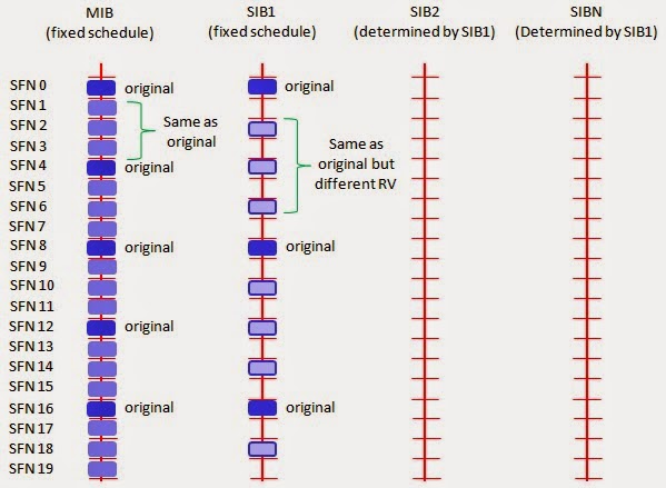
In LTE, MIB, SIB1, SIB2 is mandated to be transmitted for any cells. Since many of the SIB are transmitted, it should be transmitted in such a way that the location (subframe) where a SIB is transmitted should not be the same subframe where another SIB is transmitted. Overall SIB Scheduling concept is as follows. As you see i) MIB is transmitted at a fixed cycles (every 4 frames starting from SFN 0) ii) SIB1 is also transmitted at the fixed cycles (every 8 frames starting from SFN 0). iii) All other SIB are being transmitted at the cycles specified by SIB scheduling information elements in SIB1 You may notice that LTE SIB1 is very similar to WCDMA MIB. Especially at initial test case development, you have to be very careful about item v). If you set this value incorrectly, all the other SIBs will not be decoded by UE. And as a result, UE would not recognize the cell and show "No Service" message. According to 36.331 section 5.2.1.2, the MIB scheduli...

TFI and TFCI

TFI stands for Transport Format Indicator TFCI stands for Transport Format Combination Indicator. As you see in the following diagram each Transport Block has one TFI attached to it. In physical layer, multiple transport blocks are combined into a large 'transmission frame'. This combined transmission frame is called Coded Composite Transport Channel (CCTrCh). Each CCTrCH frame gets its own indicator which is called TFCI. TFI plays roles as follows. The TFI is a label for a specific transport format within a transport format set. It is used in the inter-layer communication between MAC and L1 each time a transport block set is exchanged between the two layers on a transport channel. When the DSCH is associated with a DCH, the TFI of the DSCH also indicates the physical channel (i.e. the channelisation code) of the DSCH that has to be listened by a UE TFCI plays roles as follows. This is a representation of the current Transport F...

Scrambling Code in WCDMA

Image
Let's suppose you are a NodeB. You will getting various signals from many different users (UEs) all at the same time. Then how would you differentiate the incoming signals into separate users at the very low level of your hardware ?. Of course you can figure out exactly which user you are dealing with at higher layer with various type of user ID (UE ID), but my question is how to figure out each user at PHY layer ? Now let's assume that you are a UE. You may be hearing many signals from multiple NodeBs simultaneously. Then how would you differentiate the incoming signals into separate NodeB at the very low level of your hardware ? The answer to both of the question is same. It is "Scrambling Code". By using the scrambling code, NodeB can separate signals coming simultaneously from many different UEs and UE can separate signals coming simultaneously from many different NodeB. Now let's look into how/where the scrambling code works. Following illu...

PRACH Power

Initial PRACH (The first PRACH that UE transmit) is determined by the following formula. Initial RACH Preamble Power = Primary CPICH TX Power – CPICH_RSCP + UL_Interference + Constant Value CPICH_RSCP is the power directly measured by UE and all other parameters are calculated (obtained) from system information. The related parameter and system information is as follows. System Information Information Element Example Value SIB3 Maximum Allowed UL Tx Power 21 dBm SIB5 Primary CPICH Power -8 dBm Power Ramp Step 3 dB Mmax 2 NB01min 10 NB02max 10 SIB7 UL Interference -92 If UE fail to get AICH for the PRACH, it increment the PRACH power by Power Ramp Step (SIB5) and transmit the PRACH again. UE repeat this process until it gets AICH or it retried the specific number specifi...

HARQ - HSDPA

Image
 HARQ process in HSADPA goes as illustrated below. In reality with high throughput condition, multiple HARQ processes (Usually 5 HARQ processes) are running in parallel in interleaved manner to achieve high data rate. i)   HS-SCCH   is transmitted 2 slots before HS-DSCH (Refer to 7.8 HS-SCCH/HS-PDSCH timing of 25.211). ii) HS-DSCH carrying user data is transmitted. iii) UE decode it and send ACK/NACK via HS-DPCCH.

Cell Selection Procedure

Image
There are two types of Cell Selections. "Initial Cell Selection" and "Stored Information Cell Selection". Definition of these two methods are described as follows in  25.304 5.2.3 Cell Selection Process. a) Initial Cell Selection This procedure requires no prior knowledge of which RF channels are UTRA carriers. The UE shall scan all RF channels in the UTRA bands according to its capabilities to find a suitable cell. On each carrier, the UE need only search for the strongest cell. Once a suitable cell is found this cell shall be selected. b) Stored Information Cell Selection This procedure requires stored information of carrier frequencies and optionally also information on cell parameters, e.g. scrambling codes, from previously received measurement control information elements. Once the UE has found a suitable cell the UE shall select it. If no suitable cell is found the Initial cell selection procedure shall be started. Cell Selection Criteri...

Cell Search Procedure in WCDMA

Cell Search procecess in WCDMA would be described as follows (For the detailed understanding, I would recommend you to study each of the physical channels involved in the following description). i) Every cell is tranmitting its scrambling code(Primary Scrambling Code) via CPICH. ii) UE detect the cell power, primary scrambling code and some addition info for compensating demodulation process iii) UE detect P-SCH (Primary Synchronization Code) and figure out slot boundary (start and end of each slot) iv) UE detect S-SCH (Primary Synchronization Code) and figure out frame bounday (start and end of each frame) v) UE detect P-CCPCH and decode MIB. Through this MIB, UE can figure out SFN.

CQI

CQI stands for Channel Quality Indicator. As the name implies, it is an indicator carrying the information on how good/bad the communication channel quality is. This CQI is for HSDPA. (LTE also has CQI for its own purpose). CQI is the information that UE sends to the network and practically it implies the following two i) Current Communication Channel Quality is this-and-that.. ii) I (UE) wants to get the data with this-and-that transport block size, which in turn can be directly converted into throughput In HSDPA, the CQI value ranges from 0 ~ 30. 30 indicates the best channel quality and 0,1 indicates the poorest channel quality. Depending which value UE reports, network transmit data with different transport block size. If network gets high CQI value from UE, it transmit the data with larger transport block size and vice versa. What if network sends a large transport block even though UE reports low CQI, it is highly probable that UE failed to decode it (cause ...

FDD in LTE

Image
Overview   - FDD The highest level view from 36.211 for FDD LTE is as follows. It only shows the structure of one frame in time domain. It does not show any structure in frequency domain. Some of high level description you can get from this figure would be i) Time duration for one frame (One radio frame, One system frame) is 10 ms. This means that we have 100 radio frame per second. ii) the number of samples in one frame (10 ms) is 307200 (307.200 K) samples. This means that the number of samples per second is 307200 x 100 = 30.72 M samples. iii) Number of subframe in one frame is 10. iv) Number of slots in one subframe is 2. This means that we have 20 slots within one frame. So one slot is the smallest structure in time domain ? No, if you magnify this frame structure one step further, you would get the following figure. Now you see that one slot is made up of 7 small blocks called 'symbol'. (One symbol is a certain time span of signal that carry o...