SS7


Definition:

Signaling System 7 (SS7) is an architecture for  performing out-of-band signaling in support of the call-establishment, billing, routing, and information-exchange functions of the public switched telephone network (PSTN). It identifies functions to be performed by a signaling system network and a protocol to enable their performance.

What is Signaling?
Signaling refers to the exchange of information between call components
required to provide and maintain service.

Long Code in CDMA


Long code in CDMA is a chip sequence which is 240 chips long, which repeats every 41.4 days. Its primary purpose is to assist in spreading the signal, to make spread spectrum work more efficiently. The Long code used on the reverse link is usually modified using the phone's ESN when in a call. See Long Code Mask.

WCDMA Basic

Download the WCDMA Basic document   Click here to Download 

Fading


FADING in Telecomunication
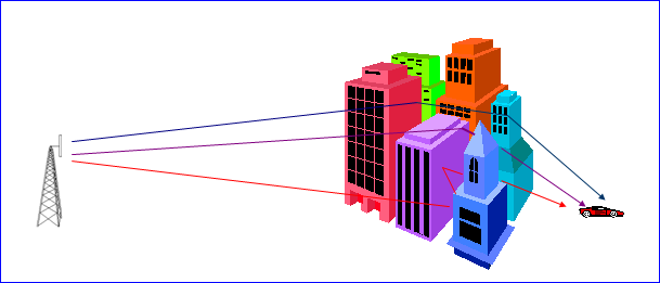
          The communication between the base station and mobile station in mobile systems is mostly non-LOS.
          The LOS path between the transmitter and the receiver is affected by terrain and obstructed by buildings and other objects.
          The mobile station is also moving in different directions at different speeds.
          The RF signal from the transmitter is scattered by reflection and diffraction and reaches the receiver through many non-LOS paths.
This non-LOS path causes long-term and short term fluctuations in the form of log-normal fading and rayleigh and rician fading, which degrades the performance of the RF channel

LONG TERM FADING
          Terrain configuration & man made environment causes long-term fading.
          Due to various shadowing and terrain effects the signal level measured on a circle around base station shows some random fluctuations around the mean value of received signal strength.
          The long-term fades in signal strength, r, caused by the terrain configuration and man made environments form a log-normal distribution, i.e the mean received signal strength, r, varies log-normally in dB if the signal strength is measured over a distance of at least 40l.
          Experimentally it has been determined that the standard deviation, s, of the mean received signal strength, r, lies between 8 to 12 dB  with the higher s generally found in large urban areas.

RAYLEIGH FADING
          This phenomenon is due to multipath propagation of the signal.
          The Rayleigh fading is applicable to obstructed propagation paths.
          All the signals are NLOS signals and there is no dominant direct path.
          Signals from all paths have comparable signal strengths.
          The instantaneous received power seen by a moving antenna becomes a random variable depending on the location of the antenna.


RICEAN FADING
          This phenomenon is due to multipath propagation of the signal.
          In this case there is a partially scattered field.
          One dominant signal.
          Others are weaker.


DOPPLERS SHIFT
          Dopplers shift is the shift in frequency due to the motion of mobile from the actual carrier frequency.
          Consider a mobile moving at a constant velocity v along a path segment having a length d between points X and Y while it receives signal from a remote source S.
          The Change in frequency due to dopplers shift is given by
                        fd = (v/l) * cos(f)
          It can be seen from the above equation that if the mobile is moving towards the direction of arrival of wave the dopplers shift is positive I.e. the apparent received frequency is increased. .

EGDE - Enhanced Data rates for GSM Evolution


(E)GPRS Network Infrastructure


How to calculate what
          No. of EGPRS resources used in 1 sector * No. of sectors : 2 x 3
           No. of time slot/sector * no of time slot used for EDAP :- 2 * 3 = 6
          So total time slots per site 6 + 6 = 12
          1 NSEI support 256 time slot with upgrade % as 10 so total no of time slots which can be equipped is 256 - 10% of 256 = 230.4 ~ 230
          So no. of sites per NSEI is 230/12 = 19.16 ~ 19
          So no NSEI required / BSC :  100 / 19 = 5.2 +1 (for future use) ~ 6
          2 NSEI supports 1 BCSU so no. of PCU required : 6/2 = 3
          No. of NSEI required is equivalent to the no. of Gb link = 3
          On 1 E1 we can get 31x64 = 1984 , so access rate can be given by 1 E1 = 1984/ access rate (256) = 1984 / 256  ~  7

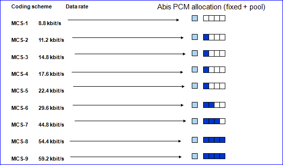
Transmission requirement for EGPRS coding schemes in Abis interface


EDGE modulations

  
Scheme
Modulation
Maximum rate [kb/s]
MCS-9


8PSK
59.2
MCS-8
54.4
MCS-7
44.8
MCS-6
29.6 / 27.2
MCS-5
22.4
MCS-4


GMSK
17.6
MCS-3
14.8 / 13.6
MCS-2
11.2
MCS-1
8.8

 
 EDAP utilization
          6 EGPRS RTSLs (Dedicated + Default territory)
           50 % utilization assumed (3 Data Erlangs traffic)
           On average 3 RTSLs used


          RTSLs use MCS7 (44.8 kbit/s) with average C/I=13dB and throughput 30kbit/s
           Effective data rate factor excluding retransmissions over the air-interface is 30/44.8 ~ 0.7
           Slave group utilization is 0.7*0.5= 0.35


Inter-RAT Handover ( IRAT Handover)


The 2G/3G inter-RAT handover involves the handover from GSM to UMTS and the handover from UMTS to GSM. The handover is controlled mainly by the network. For MSs in dedicated mode, inter-RAT handovers can be performed, including the emergency handover, better cell handover, inter-RAT load handover, and inter-RAT service handover.

Inter-RAT Handover from UMTS to GSM
MSs in dedicated mode can be handed over from a UMTS cell to a GSM cell. The handover decision and handover procedure are controlled by the RNC. The BSS considers the incoming handover from UMTS to GSM as a common inter-BSC handover.
 The parameter Inter-RAT In BSC Handover Enable determines whether inter-RAT handover from UMTS to GSM is enabled. If Inter-RAT In BSC Handover Enable is set to No, the BSS rejects all the requests for the handover from UMTS to GSM.

Inter-RAT Handover from GSM to UMTS
The parameter Inter-RAT In BSC Handover Enable determines whether the inter-RAT handover from GSM to UMTS is enabled. If Inter-RAT In BSC Handover Enable is set to NO(No), the BSS rejects all the requests for the handover from GSM to UMTS and does not select a UMTS cell as the target cell.


In dedicated mode, an MS obtains the list of neighboring UMTS cells and other information from the Measurement Information. Then, the MS reports the measurement result to the BSS through the measurement report. After receiving the measurement result, the BSS determines whether to initiate the inter-RAT handover from GSM to UMTS based on the measurement result and the handover algorithm.

Evolved Node B (eNB)


Inter-cell RRM: HO, load balancing between cells
Radio Bearer Control: setup, modifications and release of Radio Resources
Connection Mgt. Control: UE State Management, MME-UE Connection
Radio Admission Control
eNode B Meas. collection and evaluation
Dynamic Resource Allocation (Scheduler)
IP Header Compression/ de-compression
Access Layer Security: ciphering and integrity protection on the radio interface
MME Selection at Attach of the UE
User Data Routing to the SAE GW
Transmission of Paging Msg coming from MME

Transmission of Broadcast Info (e.g. System info, MBMS)