Antenna RF Diplexer

The antenna diplexer or RF diplexer splitter / combiner used for combining and splitting RF fees so they can be used by multiple transmitters of receivers and possibly on different frequencies.
An Antenna diplexer is a unit that in one application can be used to enable more than one transmitter to operate on a single RF Antenna. Sometimes these units may be called Antenna duplexers. Typically an Antenna diplexer would enable transmitters operating of different frequencies to use the same Antenna. In another application, an Antenna diplexer may be used to allow a single Antenna to be used for transmissions on one band of frequencies and reception on another band.
Antenna diplexers find many uses. In one common example an Antenna diplexer or RF diplexer is used in a cellular base station to allow it to transmit and receive simultaneously. The Antenna diplexer enables the same Antenna system to be used while preventing the transmitted signal from reaching the receiver and blocking the input. In another application a diplexer may be used by a broadcast station transmitting on several different frequencies at the same time using the same Antenna. The use of the diplexer enables a single Antenna to be used, while preventing the output from one transmitter being fed back into the output of the other.
Small Antenna diplexers may be used in domestic environments to allow several signals to run along a single feeder. In one application this may allow a single feeder to be used for television and VHF FM radio reception, or to allow terrestrial television signals and this from a satellite low noise box (LNB) to pass down the same lead. These RF diplexers are normally relatively low cost as the specifications are not nearly as exacting as those used for professional RF diplexer installations.


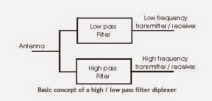
Basic Antenna diplexer concepts
There are a number of ways of implementing RF diplexers. They all involve the use of filters. In this way the paths for the different transmitters and receivers can be separated according to the frequency they use. The simplest way to implement a diplexer is to use a low pass and a high pass filter although band-pass filters may be used. In this way the diplexer routes all signals at frequencies below the cut-off frequency of the low pass filter to one port, and all signals above the cut-off frequency of the high pass filter to the other port. Also here is no path from between the two remote connections of the filters. All signals that can pass through the low pass filter in the diplexer will not be able to pass through the high pass filter and vice versa.


A further feature of an RF diplexer is than it enables the impedance seen by the receiver or transmitter to remain constant despite the load connected to the other port. If the filters were not present and the three ports wired in parallel, neither the Antenna nor the two transmitter / receiver ports would see the correct impedance.


RF diplexer filter requirements
When designing an Antenna diplexer a number of parameters must be considered. One is the degree of isolation required between the ports labelled for the high and low frequency transmitter / receiver. If the diplexer is to be used purely for receiving, then the requirement for high levels of isolation is not so high. Even comparatively simple filters give enough isolation to ensure each receiver sees the right impedance and the signals are routed to the correct input without any noticeable loss. Even levels of isolation of 10 dB would be adequate for many installations. For diplexers that are used to split and combine television and VHF FM radio along a single line, te levels of isolation are likely to be very low.
The next case is when the diplexer is to be used for transmitting only. It will be necessary to ensure that the levels of power being transferred back into a second transmitter are small. Power being fed into the output of a transmitter in this way could give rise to intermodulation products that may be radiated and cause interference. It is also important to ensure that the transmitters see the correct impedance, and that the presence of the second transmitter does not affect the impedance seen by the first. Typically levels of isolation between the transmitter ports of 60 - 90 dB may be required.
The final case is where one of the ports is used for transmitting, and the other for receiving simultaneously. In this instance very high levels of isolation are required to ensure that the minimum level of the transmitter power reaches the receiver. If high levels of the transmitter signal reach the receiver, then it will be desensitised preventing proper reception of the required signals. Levels of isolation in excess of 100 dB are normally required for these applications.

Band pass filters
Under some circumstances band pass filters may be used. These may be used where comparatively narrow bandwidth is required for either or both of the transmitter / receiver ports. Sometimes a very high Q resonant circuit may be used. By using this approach high degrees of rejection can be achieved. Often repeater stations which receive on one channel and transmit on another simultaneously use diplexers that utilise this approach.


LTE Interview Question and Answer ( QA)

1. What is LTE?
2. What's the difference between 2G, 3G & LTE?
3. What's the benefit of LTE?
4. What's technology applied in LTE? (Both in UL and DL).
5. What is LTE Architecture?
6. What is the EUTRAN?
7. What is LTE Network Interface?
8. What is LTE Network Element?
9. What's the maximum Throughput we can achieve from LTE?
10. In the market, which type/category of UE is available now?
11. Do you have any experience in LTE dimensioning/planning and Drive-testing?
12. What is main frequency band for LTE?
13. In coverage planning, what are the most influence factors?
14. In 3G, RSCP and Ec/Io are used to determine in coverage planning. How's about in LTE? And why?
15. What are the range of SINR, RSRP, RSRQ, MCS and CQI values?
16. What is the typical cell range of LTE?
17. How do you understand RB and how does RB impact on Throughput?
18. What is the typical value of latency?
19. Do we still need Scraming code planning in LTE? If not, why?
20. Please explain me about eNodeB, MME and core network layout.
21. For capacity planning, do we still need Channel element (CE) dimensioning? If not, why?
22. Have you experience in Atoll and Momentun?
23. Have you experience in XCAL and Agilent NiXT?
24. Please explain me about QoS and Scheduling in LTE?
25. Pls. explain me about MIMO, SIMO and TxDiV configuration?
26. How's about those configuration and expected throughput?
27. What are the types of HO? If so, pls. explain me a bit of best cell HO and coverage HO?
28. What is ANR in LTE?
29. What is SON and how does work in LTE?
30. How does Timing advance(TA) works in LTE?


Latest Position 28-SEP


1. Position for OSS SOLUTION ARCHITECT Click Here Location : China


2. Position for RF NPO Click Here Location : India ( Chennai).

3. Position for .NET DEVELOPER  Click here location : England


Remote OMT


The Remote OMT Over IP is used to remotely perform OMT functionality from a TCP/IP network connecting BSCs.
The Remote OMT Over IP is mainly used for:
  • Getting detailed information about an RBS 2000 - The information can be used to remotely verify that an RBS 2000 is correctly configured and to perform preventive maintenance.
  • Fault localization of an RBS 2000 - Experts can use the Remote OMT Over IP to perform fault localization and to guide service personnel at site
  • Restart of a whole RBS 2000 or a part of an RBS 2000 - The same type of restart that is achieved by pushing a reset button in an RBS 2000 can be performed with the Remote OMT Over IP. This may be useful in situations with abnormal RBS behavior
  • Retrieve detailed information about an RBS 2000 remotely from a TCP/IP network connecting BSCs.
  • Perform fault localization of an RBS 2000 remotely from a TCP/IP network connecting BSCs. This means that it will be easier to prepare for a site visit and it will be possible for experts to remotely guide service personnel at site.
  • It is possible for a BSC to simultaneously handle four Remote OMT Over IP sessions. (Only one Remote OMT Over IP can simultaneously be connected to one specific RBS).
  • Perform "hardware reset" of an RBS 2000 remotely from a TCP/IP network connecting BSCs
  • The signalling is embedded in the LAPD signalling. A whole time slot does not have to be allocated for the OMT signalling as for Remote OMT.
  • It is much easier to establish a connection for the OMT signalling as it is not needed to setup a path in the transmission network. Just an access to the IP network connected to the BSC is needed.
  • The Remote OMT Over IP does not have to be equipped with any special hardware equipment as for Remote OMT which have to be equipped with a special communication board to emulate an E1/T1 transmission link.

The Remote OMT Over IP is an optional feature activated by the BSC.
The Remote OMT Over IP user is required to make an authentication by providing a password to be able to make a connection to the RBS. The password is defined by the BSC operator at the setup of the feature. It is also possible to define how long time the feature shall be activated and also to define the IP-address which the calling Remote OMT Over IP is supposed to have.

Benefits
Remote OMT Over IP makes it possible to:
Benefits with Remote OMT Over IP compared to Remote OMT:

what is Wimax

WiMAX is one of the hottest broadband wireless technologies around today. WiMAX systems are expected to deliver broadband access services to residential and enterprise customers in an economical way.
Loosely, WiMax is a standardized wireless version of Ethernet intended primarily as an alternative to wire technologies (such as Cable Modems, DSL and T1/E1 links) to provide broadband access to customer premises.


More strictly, WiMAX is an industry trade organization formed by leading communications, component and equipment companies to promote and certify compatibility and interoperability of broadband wireless access equipment that conforms to the IEEE 802.16 and ETSI HIPERMAN standards.
WiMAX would operate similar to WiFi but at higher speeds over greater distances and for a greater number of users. WiMAX has the ability to provide service even in areas that are difficult for wired infrastructure to reach and the ability to overcome the physical limitations of traditional wired infrastructure.
WiMAX was formed in April 2001, in anticipation of the publication of the original 10-66 GHz IEEE 802.16 specifications. WiMAX is to 802.16 as the WiFi Alliance is to 802.11.
WiMAX is:
·         Acronym for Worldwide Interoperability for Microwave Access.
·         Based on Wireless MAN technology.
·         A wireless technology optimized for the delivery of IP centric services over a wide area.
·         A scaleable wireless platform for constructing alternative and complementary broadband networks.
·         A certification that denotes interoperability of equipment built to the IEEE 802.16 or compatible standard. The IEEE 802.16 Working Group develops standards that address two types of usage models:
o    A fixed usage model (IEEE 802.16-2004).
o    A portable usage model (IEEE 802.16e).

What is 802.16a ?

WiMAX is such an easy term that people tend to use it for the 802.16 standards and technology themselves, although strictly it applies only to systems that meet specific conformance criteria laid down by the WiMAX Forum.
The 802.16a standard for 2-11 GHz is a wireless metropolitan area network (MAN) technology that will provide broadband wireless connectivity to Fixed, Portable and Nomadic devices.
It can be used to connect 802.11 hot spots to the Internet, provide campus connectivity, and provide a wireless alternative to cable and DSL for last mile broadband access.

WiMax Speed and Range:

WiMAX is expected to offer initially up to about 40 Mbps capacity per wireless channel for both fixed and portable applications, depending on the particular technical configuration chosen, enough to support hundreds of businesses with T-1 speed connectivity and thousands of residences with DSL speed connectivity. WiMAX can support voice and video as well as Internet data.
WiMax will be to provide wireless broadband access to buildings, either in competition to existing wired networks or alone in currently unserved rural or thinly populated areas. It can also be used to connect WLAN hotspots to the Internet. WiMAX is also intended to provide broadband connectivity to mobile devices. It would not be as fast as in these fixed applications, but expectations are for about 15 Mbps capacity in a 3 km cell coverage area.
With WiMAX users could really cut free from today's Internet access arrangements and be able to go online at broadband speeds, almost wherever they like from within a MetroZone.
WiMAX could potentially be deployed in a variety of spectrum bands: 2.3GHz, 2.5GHz, 3.5GHz, and 5.8GHz

Why WiMax ?

·         WiMAX can satisfy a variety of access needs. Potential applications include extending broadband capabilities to bring them closer to subscribers, filling gaps in cable, DSL and T1 services, WiFi and cellular backhaul, providing last-100 meter access from fibre to the curb and giving service providers another cost-effective option for supporting broadband services.
·         WiMAX can support very high bandwidth solutions where large spectrum deployments (i.e. >10 MHz) are desired using existing infrastructure keeping costs down while delivering the bandwidth needed to support a full range of high-value multimedia services.
·         WiMAX can help service providers meet many of the challenges they face due to increasing customer demands without discarding their existing infrastructure investments because it has the ability to seamlessly interoperate across various network types.
·         WiMAX can provide wide area coverage and quality of service capabilities for applications ranging from real-time delay-sensitive voice-over-IP (VoIP) to real-time streaming video and non-real-time downloads, ensuring that subscribers obtain the performance they expect for all types of communications.
·         WiMAX, which is an IP-based wireless broadband technology, can be integrated into both wide-area third-generation (3G) mobile and wireless and wireline networks allowing it to become part of a seamless anytime, anywhere broadband access solution.
Ultimately, WiMAX is intended to serve as the next step in the evolution of 3G mobile phones, via a potential combination of WiMAX and CDMA standards called 4G.

WiMAX Goals:

A standard by itself is not enough to enable mass adoption. WiMAX has stepped forward to help solve barriers to adoption, such as interoperability and cost of deployment. WiMAX will help ignite the wireless MAN industry by defining and conducting interoperability testing and labeling vendor systems with a "WiMAX Certified™" label once testing has been completed successfully.


What is Wi-Fi


Wi-Fi stands for Wireless Fidelity. Wi-Fi is based on the Institute of Electrical and Electronics Engineers' (IEEE) 802.11 standards Wi-Fi has become the defacto standard for last feet broadband connectivity in homes, offices, and public hotspot locations. systems can typically provide a coverage range of only about 1,000 feet from the access point.


Wi-Fi offers remarkably higher peak data rates than do 3G systems, primarily since it operates over a larger 20MHz bandwidth, but Wi-Fi systems are not designed to support high-speed mobility.
One significant advantage of Wi-Fi over WiMAX and 3G is the wide availability of terminal devices. A vast majority of laptops shipped today have a built-in Wi-Fi interface. Wi-Fi interfaces are now also being built into a variety of devices, including personal data assistants (PDAs), cordless phones, cellular phones, cameras, and media players.
The WiFi standards define a fixed channel bandwidth of 25 MHz for 802.11b and 20 MHz for either 802.11a or g networks. 
All Wi-Fi networks are contention-based TDD systems, where the access point and the mobile stations all vie for use of the same channel. Because of the shared media operation, all Wi-Fi networks are half duplex.
There are equipment vendors who market Wi-Fi mesh configurations, but those implementations incorporate technologies that are not defined in the standards.

Range:
Wi-Fi networks have limited range. A typical wireless access point using 802.11b or 802.11g with a stock antenna might have a range of 35 m (115 ft) indoors and 100 m (330 ft) outdoors


LTE Advanced Key Features

LTE refers to the advanced version of LTE that is being developed by 3GPP to meet or exceed the requirements of the International Telecommunication Union (ITU) for a true fourth generation radio-communication standard known as IMT-Advanced. 4G LTE, whose project name is LTE-Advanced, is being specified initially in Release 10 of the 3GPP standard, with a functional freeze targeted for March 2011.
Following is the Key Features for LTE Advanced:
§  Peak data rates: Downlink – 1 Gbps and  Uplink – 500 Mbps.
§  Spectrum efficiency: 3 times greater than LTE.
§  Peak spectrum efficiency: Downlink – 30 bps/Hz; Uplink – 15 bps/Hz.
§  Spectrum use: the ability to support scalable bandwidth use and spectrum aggregation where non-contiguous spectrum needs to be used.
§  Latency: from Idle to Connected in less than 50 ms and then shorter than 5 ms one way for individual packet transmission.
§  Cell edge user throughput to be twice that of LTE.
§  Average user throughput to be 3 times that of LTE.
§  Mobility: Same as that in LTE
§  Carrier Aggregation
§  Higher order MIMO
§  Relay nodes and Heterogeneous networks
§  Enhanced Inter-Cell Interference Coordination
§  Coordinated Multipoint (CoMP) Transmission – Formalized in 3GPP Release 11