|
Home
|
Move to column A
|
|
Tab
|
Navigate a cell - right
|
|
Shift + Tab
|
Navigate a cell - left
|
|
Ctrl + Arrow
|
Move to edge of current data
region
|
|
End + Arrow
|
Move to edge of current data
region
|
|
Shift + Arrow
|
Navigate a cell - all arrow
directions - with selection
|
|
Ctrl + Home
|
Move to the beginning of the
Worksheet
|
|
Ctrl + End
|
Move to the end of the
Worksheet
|
|
Alt + Page Down
|
Move one screen to right
|
|
Alt + Page Up
|
Move one screen to left
|
|
Ctrl + Page Down
|
Move to the next worksheet
|
|
Ctrl + Page Up
|
Move to the previous worksheet
|
|
F6
|
Move to the next pane in split
worksheet
|
|
Shift + F6
|
Move to the previous pane in
split worksheet
|
|
Ctrl + .
|
Move to the corners of
selection and verify your selection
|
|
Ctrl + `
|
Switch between value and
formula
|
|
Alt + T, U, T
|
Trace Precedents
|
|
Alt + T, U, D
|
Trace Dependents
|
|
Alt + T, U, A
|
Remove all arrows
|
|
Ctrl + [ or Ctrl + ]
|
Switch to Data Sheet from the
formula or vice-versa
|
|
Editing
|
|
|
F2
|
Edit cell contents
|
|
Shift + F2
|
Edit/Create a cell comment
|
|
Delete
|
Delete cell contents
|
|
Ctrl + -
|
Delete selected row or column
|
|
Ctrl + Delete
|
Delete all text to the right
of current editing
|
|
Alt + Enter
|
Enter a new line while editing
in the same cell - word wrap
|
|
Ctrl + +
|
Insert a row or column before
selection (row/column selection)
|
|
Ctrl + Shift + A
|
Type a function; press combo;
inserts function syntax
|
|
Ctrl + Enter
|
Select range; enter
data/function; press combo; copies to selection
|
|
Shift + Enter
|
Stop editing and move a cell
up
|
|
Ctrl + Alt + V
|
Paste Special (Version 2007
and above)
|
|
Ctrl + F3
|
Define names
|
|
Shift + F3
|
Open all functions dialog box
|
|
Ctrl + A
|
Display a function window for
the typed function
|
|
Ctrl + D
|
Copy down the selection
|
|
Ctrl + R
|
Copy to the right in the
selection
|
|
Ctrl + Shift + "
|
Copy contents of above cell in
the current cell and edit
|
|
Ctrl + ;
|
Enter Date
|
|
Formatting
|
|
|
Ctrl + 1
|
Display Format Cells dialog
box
|
|
Ctrl + Shift + ~
|
Apply number format
|
|
Ctrl + Shift + !
|
Apply number format
|
|
Ctrl + Shift + $
|
Apply currency format
|
|
Ctrl + Shift + %
|
Apply percentage format
|
|
Ctrl + Shift + #
|
Apply date format
|
|
Ctrl + Shift + &
|
Apply outline border
|
|
Ctrl + Shift + _
|
Remove outline border
|
|
Selection
|
|
|
Ctrl + Shift + *
|
Select data region around
current cell
|
|
Shift + Home
|
Extend selection to beginning
of row
|
|
Shift + Spacebar
|
Select entire row
|
|
Ctrl + Spacebar
|
Select entire column
|
|
F8
|
Turn on/off selection mode;
then start moving around
|
|
Shift + F8
|
Multi-select - select range;
press combo; select another range; repeat
|
|
Alt+;
|
Select visible cells (ignores
hidden rows/columns in the selection)
|
MS-Excel Short Key
Transcoder Controller (TRC)
The purpose of a TRC is to multiplex network traffic channels from multiple
BSCs onto one 64 Kbits/s PCM channel which reduces network transmission costs.
FUNCTION OF MSC:-
1. Switching and call
routing
2. Charging
3. Service
provisioning
4. Communication with
HLR
5. Communication with
the VLR
6. Communication with
other MSC’s
7. Control of
connected BSC’s
8. Direct access to
Internet services
RF Optimization Processes
Network
Optimization process involves the following activities:
- FIRST SET THE CRITERION (GOAL) OF OPTIMIZATION PROCESS
- BASELINE & TARGET KPI’s.
- DELIVERABLES
- CONDUCTING A BASELINE PHYSICAL AUDIT
- REMOVING ALL SERVICE AFFECTING ALARMS
- IDENTIFYING POOR COVERAGE AREAS
- IDENTIFYING CAPACITY CONSTRAINTS &
OVERUTILIZED CELLS
- VARIOUS KPIs with Root-Cause-Analysis of
problems.
- Frequency Plan (BCCH & TCH)
- Neighbor plan
- CONDUCTING A GSM SYSTEM PARAMETERS AUDIT
- Deliverables of an Optimization activity:
- Baseline Drive test comparison with post
implementation results.
- Statistical comparison of baseline &
improved network.
- Parameter Audit report.
- Physical parameter inconsistencies.
- Frequency & neighbor plan inconsistencies
- Recommendations for
- Coverage
- Capacity
- Physical Optimization
- Location Area Optimization.
Ericsson Certified Associate – Radio Access Networks - ECP-362
Sections Section/Objective Title
Section 1 RAN Fundamentals 26%
Objective
1.1 Describe the general RAN architecture
Objective
1.2 Describe the RAN services
Objective
1.3 Describe Radio design principles
Objective
1.4 Describe air interface principles
Objective
1.5 Describe signaling, protocols and layers
Objective
1.6 Describe Radio Network functionalities
Objective
1.7 Describe Radio Network Performance
Section 2 RAN Technologies 27%
Objective
2.1 Describe the fundamentals of GSM
Objective
2.2 Describe the fundamentals of WCDMA
Objective
2.3 Describe the fundamentals of LTE
Section 3 RAN Evolution 10%
Objective
3.1 Identify Ericsson RAN product and services portfol
Objective
3.2
Describe
how different radio technologies contribute together to mobile
operators
business evolution
Objective
3.3 Identify how multi-RAN products add value to Radio Access Network
Section 4 Radio Base Station and Site Solution 17%
Objective
4.1 Identify Site Solution equipment needed for a RBS site
Objective
4.2 Describe different concepts for in-building coverage and/or capacity
Objective
4.3 Identify ways to reduce site OPEX
Objective
4.4 Identify different RBS types and hardware
Section 5 RAN Transport 11%
Objective
5.1 Describe the architecture and interfaces
Objective
5.2 Describe synchronization solutions
Objective
5.3 Describe values with IP RAN
Objective
5.4 Describe transport characteristics, QoS, and capacity
Section 6 RAN Controllers 9%
Objective
6.1 Describes the role of the BSC
Objective 6.2 Describes
the role of the RNC
Ericsson Certified Associate – Radio Network Design - ECP-371
Sections Section/Objective Title
Section 1 Cellular Technologies 17%
Objective
1.1 Identify cellular industry standards
Objective
1.2 Identify fundamental radio concepts
Objective
1.3 Identify cellular technologies used
Objective
1.4 Describe call procedures
Objective
1.5 Identify interference management concepts
Section 2 Air Interface Concepts 22%
Objective
2.1 Describe power calculations
Objective
2.2 Describe link budget concepts
Objective
2.3 Identify propagation concepts
Objective
2.4 Identify radio channel characteristics
Section 3 Cellular Network Architecture 11%
Objective
3.1 Identify cellular network architectures
Objective
3.2 Identify base station architectures
Objective
3.3 Identify in-building system (IBS) concepts
Section 4 Radio System Components 18%
Objective
4.1 Describe antenna concepts
Objective
4.2 Identify radio frequency systems and components
Objective
4.3 Describe radio system performance concepts
Section 5 Radio Network Design 22%
Objective
5.1 Identify high level radio network design concepts
Objective
5.2 Describe dimensioning concepts
Objective
5.3 Identify radio network performance management concepts
Objective
5.4 Identify radio network tuning (optimization) concepts
Section 6 Radio Network Design Tools 10%
Objective
6.1 Describe coverage planning tools
Objective 6.2 Describe
frequency planning tools
Ericsson Certified Associate – Radio Network Optimization - ECP-381
Sections Section/Objective Title
Section 1 Cellular Technology 10%
Objective
1.1 Identify cellular industry standards
Objective
1.2 Identify cellular technologies used
Objective
1.3 Describe call procedures
Section 2 Cellular Network Architecture 10%
Objective
2.1 Identify cellular network architectures
Objective
2.2 Identify base station architectures
Objective
2.3 Describe base station RF and baseband components
Section 3 Cellular Network Fundamental Concepts 30%
Objective
3.1 Describe GSM concepts
Objective
3.2 Describe WCDMA/CDMA concepts
Objective
3.3 Describe LTE concepts
Section 4 Optimization Activities and Procedures 35%
Objective
4.1 Identify input data sources for optimization activities
Objective
4.2 Identify installation and external interference troubleshooting
Objective
4.3 Describe physical RF optimization
Objective
4.4 Describe GSM optimization procedures
Objective
4.5 Identify Ericsson GSM features
Objective
4.6 Describe WCDMA optimization procedures
Objective
4.7 Identify Ericsson WCDMA features
Objective
4.8 Describe LTE optimization procedures
Objective
4.9 Identify Ericsson LTE features
Section 5 Radio Network Optimization Tools 15%
Objective
5.1 Describe drive test tools used for optimization
Objective
5.2 Describe physical RF cell planning optimization tools
Objective
5.3 Describe RRM optimization tools
Objective
5.4 Describe SON tools
Objective
5.5 Describe frequency planning optimization tools
Objective
5.6 Describe
neighbor and BSIC/SC/ PCI/PRACH planning optimization
tools
Objective 5.7 Describe
radio monitoring and troubleshooting tools
Satellite Antenna
Overview, of the typical RF antenna design
types used with satellites, both on the ground and on the satellite. This
includes satellite television (tv) reception.
A variety of forms of
antenna can be used for transmitting to and receiving from satellites. The most
common type of satellite antenna is the parabolic reflector, however this is
not the only type of antenna that can be used. The actual type of antenna will
depend upon what the overall application and the requirements.
Antenna
gain
The distances over
which signals travel to some satellites is very large. Geostationary ones are a
particular case. This means that path losses are high and accordingly signal
levels are low. In addition to this the power levels that can be transmitted by
satellites are limited by the fact that all the power has be generated from
solar panels. As a result the antennas that are used are often high gain
directional varieties. The parabolic reflector is one of the most popular.
Antennas
on satellites
Although there is
fundamentally no difference between the antennas on satellites and those on the
ground there are a number of different requirements that need to be taken into
account. In the first instance the environmental conditions are very different.
As conditions in space are particularly harsh the antennas need to be built to
withstand this. Temperatures vary considerably between light and dark and this
will cause expansion and contraction. The materials that are sued in the
conduction need to be carefully chosen.
The gain and
directivity of the antenna need to be chosen to meet the needs of the
satellite. For most geostationary satellites the use of directional antennas
with gain is mandatory in view of the path losses incurred. These satellites
are more likely to cover a give area of the Earth, and as they remain in the
same position this is normally not a problem. However the attitude of the
satellite and its antenna must be carefully maintained to ensure the antenna is
aligned in the correct direction. The antennas on board the satellite are
typically limited in size to around 2 - 3 metres by the space that is available
on the satellite structure.
For satellites in low
earth orbits, considerably less directive antennas are normally used. Signals
are likely to be received and transmitted over a much wider angle, and these
will change as the satellites move. Accordingly these satellites seldom use
parabolic reflector antennas.
Ground
antennas
Ground antennas used
for receing satellite signals and transmitting to the satellites vary
considerably according to their application. Again parabolic reflectors are the
most widely used, but Yagi antennas may be used on occasions.
The size of the
antennas may vary considerably. The parabolic reflectors used for satellite
television reception are very small. However those used for professional
applications are much larger and may range up to several tens of metres in
size.
The satellite antennas
are carefully chosen by the system designer to match the particular
requirements. It is possible to calculate the exact specification for the
antenna, knowing the path loss, signal to noise ratio, transmitter power
levels, receiver sensitivities, etc. A small 70 centimetre antenna may be sufficient
for direct reception of satellite TV programmes but would not be suitable for
transmitting programmes up to the satellite where a much higher signal level is
required to ensure the best possible picture is radiated back to Earth.
Satellite
television antennas
It has already been
mentioned that satellite television antennas use parabolic reflector or
"dish" antennas. They are also incorporate what is termed an LNB.
This is a Low Noise Block converter. The satellite transmits signals at
frequencies between 12.2 and 12.7 GHz. Signals at these frequencies would be
very quickly attenuated by any coaxial feeder that was used. As feeder lengths
may run into several metres or more in many installations, this would mean that
the signals that reached the television would be very weak. To overcome this
problem the LNB is installed at the feed point of the antenna. Its job is two
fold. It amplifies the signal, but more importantly it converts it down to a
frequency (usually 950 to 1450MHz) where the loss introduced by the coaxial
feeder is considerably less. The amplification provided by the LNB also enables
the loss introduced by the cable to be less critical. By performing these two
functions it means that domestic coaxial cable can be used satisfactorily,
while maintaining sufficiently high signal levels at the receiver.
Antenna RF Diplexer
The antenna
diplexer or RF diplexer splitter / combiner used for combining and splitting RF
fees so they can be used by multiple transmitters of receivers and possibly on
different frequencies.
An Antenna diplexer is a unit that in one application can be
used to enable more than one transmitter to operate on a single RF Antenna.
Sometimes these units may be called Antenna duplexers. Typically an Antenna
diplexer would enable transmitters operating of different frequencies to use
the same Antenna. In another application, an Antenna diplexer may be used to
allow a single Antenna to be used for transmissions on one band of frequencies
and reception on another band.
Antenna diplexers find many uses. In one common example an Antenna
diplexer or RF diplexer is used in a cellular base station to allow it to
transmit and receive simultaneously. The Antenna diplexer enables the same Antenna
system to be used while preventing the transmitted signal from reaching the
receiver and blocking the input. In another application a diplexer may be used
by a broadcast station transmitting on several different frequencies at the
same time using the same Antenna. The use of the diplexer enables a single Antenna
to be used, while preventing the output from one transmitter being fed back
into the output of the other.
Small Antenna diplexers may be used in domestic environments to
allow several signals to run along a single feeder. In one application this may
allow a single feeder to be used for television and VHF FM radio reception, or
to allow terrestrial television signals and this from a satellite low noise box
(LNB) to pass down the same lead. These RF diplexers are normally relatively
low cost as the specifications are not nearly as exacting as those used for professional
RF diplexer installations.
Basic Antenna diplexer concepts
There are a number of ways of implementing RF diplexers. They
all involve the use of filters. In this way the paths for the different
transmitters and receivers can be separated according to the frequency they
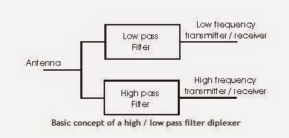
use. The simplest way to implement a diplexer is to use a low pass and a high
pass filter although band-pass filters may be used. In this way the diplexer
routes all signals at frequencies below the cut-off frequency of the low pass
filter to one port, and all signals above the cut-off frequency of the high
pass filter to the other port. Also here is no path from between the two remote
connections of the filters. All signals that can pass through the low pass
filter in the diplexer will not be able to pass through the high pass filter
and vice versa.
A further feature of an RF diplexer is than it enables the
impedance seen by the receiver or transmitter to remain constant despite the
load connected to the other port. If the filters were not present and the three
ports wired in parallel, neither the Antenna nor the two transmitter / receiver
ports would see the correct impedance.
RF diplexer filter requirements
When designing an Antenna diplexer a number of parameters must
be considered. One is the degree of isolation required between the ports
labelled for the high and low frequency transmitter / receiver. If the diplexer
is to be used purely for receiving, then the requirement for high levels of
isolation is not so high. Even comparatively simple filters give enough
isolation to ensure each receiver sees the right impedance and the signals are
routed to the correct input without any noticeable loss. Even levels of
isolation of 10 dB would be adequate for many installations. For diplexers that
are used to split and combine television and VHF FM radio along a single line,
te levels of isolation are likely to be very low.
The next case is when the diplexer is to be used for
transmitting only. It will be necessary to ensure that the levels of power
being transferred back into a second transmitter are small. Power being fed
into the output of a transmitter in this way could give rise to intermodulation
products that may be radiated and cause interference. It is also important to
ensure that the transmitters see the correct impedance, and that the presence of
the second transmitter does not affect the impedance seen by the first.
Typically levels of isolation between the transmitter ports of 60 - 90 dB may
be required.
The final case is where one of the ports is used for
transmitting, and the other for receiving simultaneously. In this instance very
high levels of isolation are required to ensure that the minimum level of the
transmitter power reaches the receiver. If high levels of the transmitter
signal reach the receiver, then it will be desensitised preventing proper
reception of the required signals. Levels of isolation in excess of 100 dB are
normally required for these applications.
Band pass filters
Under some circumstances band pass filters may be used. These
may be used where comparatively narrow bandwidth is required for either or both
of the transmitter / receiver ports. Sometimes a very high Q resonant circuit
may be used. By using this approach high degrees of rejection can be achieved.
Often repeater stations which receive on one channel and transmit on another
simultaneously use diplexers that utilise this approach.
LTE Interview Question and Answer ( QA)
1. What is LTE?
2. What's the difference between 2G, 3G & LTE?
3. What's the benefit of LTE?
4. What's technology applied in LTE? (Both in UL and DL).
5. What is LTE Architecture?
6. What is the EUTRAN?
7. What is LTE Network Interface?
8. What is LTE Network Element?
9. What's the maximum Throughput we can achieve from LTE?
10. In the market, which type/category of UE is available now?
11. Do you have any experience in LTE dimensioning/planning and Drive-testing?
12. What is main frequency band for LTE?
13. In coverage planning, what are the most influence factors?
14. In 3G, RSCP and Ec/Io are used to determine in coverage planning. How's
about in LTE? And why?
15. What are the range of SINR, RSRP, RSRQ, MCS and CQI values?
16. What is the typical cell range of LTE?
17. How do you understand RB and how does RB impact on Throughput?
18. What is the typical value of latency?
19. Do we still need Scraming code planning in LTE? If not, why?
20. Please explain me about eNodeB, MME and core network layout.
21. For capacity planning, do we still need Channel element
(CE) dimensioning? If not, why?
22. Have you experience in Atoll and Momentun?
23. Have you experience in XCAL and Agilent NiXT?
24. Please explain me about QoS and Scheduling in LTE?
25. Pls. explain me about MIMO, SIMO and TxDiV configuration?
26. How's about those configuration and expected throughput?
27. What are the types of HO? If so, pls. explain me a bit of best cell HO and coverage HO?
28. What is ANR in LTE?
29. What is SON and how does work in LTE?
30. How does Timing advance(TA) works in LTE?
Latest Position 28-SEP
1. Position for OSS SOLUTION ARCHITECT Click Here Location : China
2. Position for RF NPO Click Here Location : India ( Chennai).
3. Position for .NET DEVELOPER Click here location : England
Remote OMT

The Remote OMT Over IP is used to
remotely perform OMT functionality from a TCP/IP network connecting BSCs.
The Remote OMT Over IP is mainly
used for:
- Getting detailed information about an RBS 2000 - The information can be used to remotely verify that an RBS 2000 is correctly configured and to perform preventive maintenance.
- Fault localization of an RBS 2000 - Experts can use the Remote OMT Over IP to perform fault localization and to guide service personnel at site
- Restart of a whole RBS 2000 or a part of an RBS 2000 - The same type of restart that is achieved by pushing a reset button in an RBS 2000 can be performed with the Remote OMT Over IP. This may be useful in situations with abnormal RBS behavior
- Retrieve detailed information about an RBS 2000 remotely from a TCP/IP network connecting BSCs.
- Perform fault localization of an RBS 2000 remotely from a TCP/IP network connecting BSCs. This means that it will be easier to prepare for a site visit and it will be possible for experts to remotely guide service personnel at site.
- It is possible for a BSC to simultaneously handle four Remote OMT Over IP sessions. (Only one Remote OMT Over IP can simultaneously be connected to one specific RBS).
- Perform "hardware reset" of an RBS 2000 remotely from a TCP/IP network connecting BSCs
- The signalling is embedded in the LAPD signalling. A whole time slot does not have to be allocated for the OMT signalling as for Remote OMT.
- It is much easier to establish a connection for the OMT signalling as it is not needed to setup a path in the transmission network. Just an access to the IP network connected to the BSC is needed.
- The Remote OMT Over IP does not have to be equipped with any special hardware equipment as for Remote OMT which have to be equipped with a special communication board to emulate an E1/T1 transmission link.
The Remote OMT Over IP is an
optional feature activated by the BSC.
The Remote OMT Over IP user is
required to make an authentication by providing a password to be able to make a
connection to the RBS. The password is defined by the BSC operator at the setup
of the feature. It is also possible to define how long time the feature shall
be activated and also to define the IP-address which the calling Remote OMT
Over IP is supposed to have.
Benefits
Remote OMT Over IP makes it
possible to:
Benefits with Remote OMT Over IP
compared to Remote OMT:
Subscribe to:
Posts (Atom)