Showing posts with label LTE. Show all posts

LTE Positioning Reference Signals (PRS)

Positioning reference signals are used for OTDOA User Plane Location Support. Positioning reference signals are transmitted with a periodicity Tprs[ms], as specified by prsPeriod. At each transmission occasion the position reference signals are sent in n,subf,con consecutive DL subframes. The number of consecutive DL subframes can be specified by nConsecutiveSubframes. In the figure below an example of the transmission scheme for PRS subframes is shown. 


To minimize the interference in the PRS subframes PDSCH is not scheduled in any RB in those subframes. Also note that PBCH, PSS and SSS all have higher priority than PRS. For a configuration with two antennas, PRS is transmitted from one antenna at the time. The same antenna is used the entire PRS occasion. For more information, refer to OTDOA User Plane Location Support. The more PRS subframes, the more accurate will the OTDOA positioning be. This comes at the expense of less resource available for PDSCH. The fraction of subframes used for PRS can be calculated by the following formula:

LTE - Cell-Specific Reference Signal (CRS)

To demodulate different downlink physical channels coherently, the UE requires complex valued channel estimates for each subcarrier. Known cell-specific reference symbols are inserted into the resource grid. The cell-specific reference signal is mapped to REs spread evenly in the resource grid, in an identical pattern in every RB.

When transmitting with several antennas, each antenna must transmit a unique reference signal. When one antenna transmits its reference signal, the other antenna must be silent. The mapping of the cell-specific reference signal on the resource grid therefore depends on the antenna configuration, see Figure. The pattern of cell-specific reference signals can be shifted in frequency compared to figure below. Which one of the six possible frequency shifts to use depends on the Physical Cell Identity (PCI) sent on Primary Synchronization Signal (PSS) and Secondary Synchronization Signal (SSS).


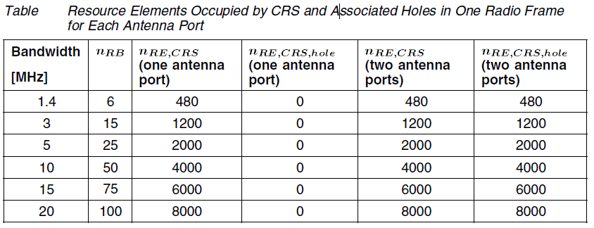
Holes are REs that must be silent because the cell-specific reference signal is transmitted on another antenna port. With one antenna port, the number of REs in one scheduling block occupied by the cell-specific reference signal and holes is 8. With two antenna ports the number is 16. The following table shows the total number of REs occupied by the cell-specific reference signal and holes, for the bandwidths available:


LTE - Resource Structure

Time Domain Structure

In the time domain, the signal is structured in the following parts:


Time Domain Signal Structure

Structure Element
Description
Radio Frames
10 ms length
Subframes
1 ms length. One frame consists of 10 subframes.
Slot
0.5 ms length. One subframe consists of two slots.
OFDM symbol
Approximately 71.4 μs length. One slot consists of 7 OFDM symbols.

  
Frequency Domain Structure
Orthogonal Frequency-Division Multiplexing (OFDM) utilize a large number of subcarriers. Each subcarrier is orthogonal to all other subcarriers. Subcarrier spacing is equal to the subcarrier bandwidth, which is 15 kHz, see Figure


Resource Element
The smallest resource unit handled in LTE consists of the combination of:
• The smallest time domain unit, one OFDM symbol
• The smallest frequency domain unit, one subcarrier

This unit is called Resource Element (RE). An RE that is not used for transmission is referred to as a hole

Resource Block
A number of REs are grouped into a physical Resource Block (RB). An RB is defined as follows:
• In the time domain: 7 OFDM symbol times (one slot)
• In the frequency domain: 12 consecutive subcarriers

Scheduling Block

A scheduling block consists of two RBs adjacent in time and with the same subcarriers. A scheduling block is the smallest unit that can be scheduled to user equipment.

LTE - Resource Block Flexible Bandwidth

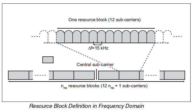
A transmitted OFDMA signal can be carried by a number of parallel subcarriers. Each LTE subcarrier is 15 kHz. Twelve subcarriers (180 kHz) are grouped into a resource block. The downlink has an unused central subcarrier. Depending on the total deployed bandwidth, LTE supports a varying number of resource blocks.
The following illustration shows resource block definition:


A resource block is limited in both the frequency and time domains. One resource block is 12 subcarriers during one slot (0.5 ms).
In the downlink, the time-frequency plane of OFDMA structure is used to its full potential. The scheduler can allocate resource blocks anywhere, even non-contiguously.
 A variant of OFDMA is used in the uplink. This variant requires the scheduled bandwidth to be contiguous, forming in effect a single carrier. The method, called SC-FDMA, can be considered a separate multiple access method.

A user is scheduled every Transmission Time Interval (TTI) of 1 ms, indicating a minimum of two consecutive resource blocks in time at every scheduling instance. The minimum scheduling in the frequency dimension is 12 subcarriers that is the width of one resource block in the frequency dimension. The scheduler is free to schedule users both in the frequency and time domain. Show in Figure as example of two users scheduled in the time and frequency domain for the downlink and the uplink:


The defined LTE bandwidths in 3GPP are the following:
In Table  Bandwidths and Resource Blocks Specified in 3GPP

Bandwidth
Number of Resource Blocks nRB
1.4 MHz
6
3.0 MHz
15
5.0 MHz
25
10.0 MHz
50
15.0 MHz
75
20.0 MHz
100


LTE - User Equipment

Five UE categories have been specified by 3GPP in User Equipment (UE) radio access capabilities, 3GPP TS 36.306. Each category is specified by a number of downlink and uplink physical layer parameter values listed in fig. 


 3GPP has in User Equipment (UE) radio transmission and reception, 3GPP TS 36.101 specified one power class, UE power class 3, that has a maximum output power of 23 dBm.

LTE RAN – Long Term Evolution Radio Access Network


The LTE RAN consists of these parts:
§  RBS
§  OSS-RC RAN components
§  Interconnecting IP transport network
The following figure shows the logical structure of a single RBS in LTE RAN and how it interconnects with other components of LTE RAN:


Logically, each RBS is comprised of sectors, a digital unit, and a support system. Each sector is connected to one or a number of antenna unit groups. Connection to other RAN and core network elements is provided by the IP transport infrastructure. In some implementations, common elements of the RBS can be shared with other technologies such as WCDMA or GSM. Refer to RBS Configurations for further details.
The following list defines terms used to describe parts of the LTE RBS:

Antenna Unit Group
An Antenna Unit Group (AUG) is the logical structure that includes all details of an antenna and associated equipment. This includes the antenna, and any associated Tower Mounted Amplifiers (TMA) and Remote Electrical Tilt (RET) equipment. An AUG may contain a single branch as in the case of a vertically polarized antenna, or it may contain two branches in the case of a cross polar antenna. Each AUG is connected to one sector. Multi-band antennas may be logically connected to more than one AUG with the different frequency band elements of the antenna connect to different AUGs.
Cell
A part of a sector with its own carrier frequency and channels within the sector frequency band. There may be up to three cells per RBS. It is possible to configure only one cell per sector.
CPRI Connection
The Common Public Radio Interface (CPRI) connection provides the communications link between the digital unit and the radio unit. The CPRI standard allows the use of either electrical or optical interface cables. Electrical cables are used for radio units installed in the RBS cabinet and optical cables are used for remote radio units.
Digital Unit LTE
The Digital Unit LTE (DUL) includes the baseband, control, and switching functions of the LTE component of the RBS. It also contains the interfaces to the RUs, IP transport and RBS synchronization. The baseband capacity is pooled to support multiple sectors. Multiple digital units can be installed in an RBS. Refer to Digital Unit Description for further details.
eNode B
The terminology used in the 3GPP standards for an RBS.
IP Transport
The IP Transport provides connectivity from the RBS to the core network, to other RBSs, and to OSS-RC. System synchronization can also be provided via the IP transport interface using the Clock Source over NTP feature. The physical IP Transport infrastructure provides a number of logical channels. Refer to Transport Network Configuration for further details.
MME
The Mobility Management Entity (MME) manages the core network control functions. The MME nodes are designed to operate in a pooled architecture. The MME handles the mobility and session management functions including:
  • UE registration and detachment handling
  • Security and Authentication, Authorization and Accounting (AAA)
  • Evolved Packet System (EPS) bearer handling
  • Mobility Anchor for active-mode UE
  • Mobility Management for idle-mode UE
OSS-RC
OSS-RC facilitates remote network management of LTE RAN.
Radio Unit
A Radio Unit (RU) refers to the physical hardware that serves a sector. Each radio unit is connected to antenna equipment that is part of an AUG. A radio unit can be physically located in the RBS cabinet, or it can be located externally to the RBS where it is referred to as a Remote Radio Unit (RRU). Refer to Radio Unit Description for further details.
Synchronization
The LTE Digital Unit uses an external synchronization source for generating the required system clock signals. The default method for synchronization is via external Global Positioning System (GPS) equipment. It is also possible to use a Network Time Protocol (NTP) time server to provide synchronization via the IP transport interface. For further details refer to Clock Source over NTP.
RET
Remote Electrical Tilt control signalling allows the antenna electrical tilt to be read or adjusted from a remote location such as from OSS-RC.
Sector
A geographical area spanned by the transmission angle from one or a group of antennas. The sector is configured to handle one specific frequency band.
SGW
The Serving Gateway (SGW) provides an interface to external networks for User Plane (UP) data. It is also anchor point for the user plane for UE mobility between RBS. The SGW also performs some Quality of Service (QoS) related signalling. The SGW nodes are designed to operate in a pooled architecture.
Support System
The Support System provides basic functions to the RBS. This can includes functions such as power supplies, battery backup, external alarms, and climate control systems. In some instances the Support System can be shared with other technologies. Refer to Support System for further details.
TMA
The Tower Mounted Amplifier (TMA) improves uplink system sensitivity and uplink coverage. TMAs are mounted close to the antenna and amplify the uplink Radio Frequency (RF) signals.

UMTS To LTE Reselection

LTE 2 reselection mechanisms are used in UMTS

Legacy Based:
This is ranking based system and it applies to intra-frequency, inter-frequency as well as for GSM reselection.

Priority Based:
This mechanism applies for cell reselection from WCDMA to LTE 
Priority based method results into 2 different scenarios:

High Priority UMTS to Low Priority LTE 
Low Priority UMTS to High Priority LTE 

Both legacy based and priority based cell reselection can be active at the same time.

Reselection from Low Priority UMTS to High Priority LTE
If LTE frequency is of higher priority than the current frequency, measurements are always performed.

Measurement Condition:
The UE searches every layer of higher priority at every Thigher_priority_search = (60*Nlayers) seconds.
Nlayers is the total number of configured higher priority E-UTRA frequencies

Reselection Condition:
Cell reselection occurs if UE finds a cell with an Srxlev value greater than ThreshHigh. 

Srxlev (target) > ThreshHigh


Reselection from High Priority UMTS to Low Priority LTE

Measurement Condition:

The UE only starts measurement for candidate LTE when following threshold is met.
Srxlev (serving) < SPrioritySearch1
Squal (serving) < SPrioritySearch2

Reselection Condition:
If Srx value of the serving cell falls below the threshServingLow value, UE attempts to reselect a cell on LTE. Cell reselection occurs if UE finds a cell with an Srxlev value greater than threshLow value for that frequency.

Srxlev (source) < ThreshServing

Low Srxlev (target) > ThreshLow

LTE Interfaces and Protocols


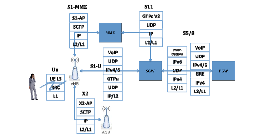
The main interfaces in LTE are Uu, S1-MME, X2, S1-U, S11 and S5.

LTE Uu: -
This is the air interface between UE and eNB. LTE layer 1 is dealt with later. RRC is the protocol that is used for communication between UE and eNB. Above RRC there is a NAS layer in UE. This NAS layer terminates at MME and eNB shall silently pass the NAS messages to MME.

LTE S1-MME: -
eNB and MME communicate using this IP interface. S1-AP is application layer interface. The transport protocols used here is SCTP. (Stream control transmission protocol)

LTE X2: -
This interface is used by a eNB to communicate to other eNB. This again is a IP interface with SCTP as transport. X2-AP is the application protocol used by eNB’s to communicate.

LTE S11: -
An IP interface between MME and SGW! GTPv2 is the protocols used at the application layer. GTPv2 runs on UDP transport. This interface must and should run GTPv2.
LTE S5: -
This is the interface between SGW and PGW. This again is an IP interface and has two variants. S5 can be a GTP interface or PMIP interface. PMIP variant is used to support non-trusted 3GPP network access.
LTE S1-U: -
User plane interface between eNB and SGW! GTP-U v1 is the application protocol that encapsulates the UE payload. GTP-U runs on UDP.

All the above IP interfaces can be of IPv4 or IPv6. Few interfaces can be of IPv4 and few can be of IPv6. From the specification side there are no restrictions.

LTE Idle Mode – Cell Reselection


After cell selection UE performs measurement and carry out cell reselection of new candidate cell. This is based on certain criterion. Reselection process involves 2 steps
1.    Measurements Condition:  Specifies when to start measuring neighboring cells. Once condition is met UE measures the RSRP level of the E-UTRA cells on the current frequency and any inter-frequency and inter-RAT frequency carriers.

2.     Reselection Condition: Specifies reselection criteria for candidate cell. There are two different mechanisms for cell reselection:
 Legacy Based
Priority Based
Cell reselection can be either Legacy or Priority based.

Legacy Based
 This is classical Ranking based system and is applied to intra-frequency reselection.
• It is also applied to inter frequencies which are equally prioritized.
• UE applies cell ranking R criterion on serving cell and neighboring cell.

Priority Based
Priority values in the range [0..7] are used, where 0 indicates lowest priority and 7 indicates highest priority.
Priorities can be set for:
Inter Frequencies: Lower, Equal or Higher Priority
Inter-Rat Frequencies: Higher or Lower Priority

Equal priorities between different RATs are not supported


Idle Mode – Cell Reselection: Priority Based
CellReselectionPriority    :           Absolute reselection priority for E-UTRA or IRAT frequency

sNonIntraSearch :           Threshold for inter and IRAT frequency
threshXLow                    :           Threshold for Srx value of serving cell below which UE performs cell
 reselection towards a lower priority cell.

threshXLow                    :           Threshold for Srx value of target cell for cell reselection towards a
                                                lower priority Inter or IRAT frequency.
tReselectionEutra           :           Cell reselection timer value for EUTRAN


tReselectionUtra :           Cell reselection timer value for UTRAN 

LTE Idle Mode Cell Selection


Once a cell meets all requirements, Criterion S is considered for cell selection.

Srxlev = [Qrxlevmeas – (Qrxlevmin + Qrxlevminoffset) – Pcompensation] > 0

Where  

Pcompensation = [max (PEMAX – PUMAX , 0)]

Example: (Ignoring Offset and Pcompensation)

Srxlev = (Qrxlevmeas –Qrxlevmin) => -105 – (-120) = 15 db > 0


Parameter

Parameter
Description
QrxLevmeas
Measured RSRP value by UE (dBm)
Qrxlevmin
Required minimum RSRP level in the cell (dBm)
Qrxlevminoffset
Offset to Qrxlevmin
PUMAX
Maximum UE power according to its class
PEMAX
Maximum UE power to be used in a cell. Ericsson equivalent is pMaxServingCell