|
Parameter Name
|
Parameter Description
|
Default Value
|
|
PagingId
|
The
value component of the RDN.
|
|
|
maxNoOfPagingRecords
|
The
maximum allowed number of paging records included in one Radio Resource
Control (RRC) paging message. It is the allowed maximum number of UE that can
be paged per paging occasion.
|
3
|
|
defaultPagingCycle
|
The
paging cycle (also referred to as T) used by the RBS and broadcast in system
information type 2. If the UE-specific Discontinuous Reception (DRX) cycle is
provided in S1AP paging and has a smaller value than defaultPagingCycle, the
UE-specific DRX cycle overrides defaultPagingCycle.
|
128
|
|
nB
|
Used
to calculate the number and position of Paging Occasions (PO) and Paging
Frames (PF).
The numerical value of nB depends on the value of the defaultPagingCycle (T) and can be set to one of the following values: 4T, 2T, T, 1/2T,1/4T, 1/8T, 1/16T, 1/32T When nB is set to T, 2T or 4T, it determines the number of POs per PF, and the PO position in PF. When nB is set to a value smaller than T, it affects the System Frame Number of the PF, the position of PO in the PF, and also distribution of UE into groups with the same PF. When nB is set to a smaller value, the groups are fewer but larger, or more but smaller. |
T
|
|
pagingDiscardTimer
|
The
length of time a received paging is retained or queued in the RBS before it
is discarded. The timer should be set to the same (or smaller) value as the
paging resend timer in MME (T3413). This setting prevents the RBS from retaining or sending
an old paging after the re-sent copy is received from the MME.
|
3
|
LTE Paging Parameter
LTE Admission Control Parameter
|
Parameter Name
|
Parameter Description
|
Default Value
|
|
paArpOverride
|
Allocation
Retention Priority level received from the Core Network that eNB interprets
as the identifier for Privileged Access.
The value zero will disable Privileged Access ARP override. |
7
|
|
ulNonGbrRatio
|
This
parameter sets the wanted uplink resource utilization ratio of Non-GBR
bearers, e.g. for Mobile Broadband users, on transport network. The value given
in this parameter specifies the Non-GBR part of the total bandwidth and the
remaining part (1-ulNonGbrRatio) sets the GBR part of the total bandwidth.
The parameter will be used by the Admission Control to balance GBR and
Non-GBR use of resources.
|
500
|
|
dlNonGbrRatio
|
This
parameter sets the wanted downlink resource utilization ratio of Non-GBR
bearers, e.g. for Mobile Broadband users, on transport network. The value
given in this parameter specifies the Non-GBR part of the total bandwidth and
the remaining part (1-dlNonGbrRatio) sets the GBR part of the total
bandwidth. The parameter will be used by the Admission Control to balance GBR
and Non-GBR use of resources.
|
500
|
|
AdmissionControlId
|
The
value component of the Relative Distinguished Name (RDN).
|
|
|
emergencyArpLimit
|
ARP
(Allocation Retention Priority) value limit used for identifying ARP values
that are considered to be part of the emergency (high priority) group. This
limit value and all values below are considered to be of high priority. The
value zero is introduced to turn off ARP handling.
|
7
|
|
nrOfBearersReserved
|
Number
of bearers reserved for high priority group (bearers with low ARP values,
Allocation Retention Priority values). Setting a high value for the
reservation means low priority bearers will always be rejected.
|
0
|
|
nrOfRrcConnectedReserved
|
Number
of RRC connections reserved for high priority UEs (handovers and where establishment
cause is emergency). Setting a high value means non emergency UEs will always
be rejected.
|
0
|
|
dlGbrAdmThresh
|
Admission
threshold for load due to Guaranteed Bit Rate (GBR) bearers in the downlink,
expressed as a fraction of the available resources.
|
1000
|
|
dlTransNwBandwidth
|
Downlink
transport network bandwidth for LTE.
|
1000
|
|
ulGbrAdmThresh
|
Admission
threshold for load due to Guaranteed Bit Rate (GBR) bearers in the uplink,
expressed as a fraction of the available resources.
|
1000
|
|
ulTransNwBandwidth
|
Uplink
transport network bandwidth for LTE.
|
1000
|
LTE Positioning Reference Signals (PRS)
Positioning
reference signals are used for OTDOA User Plane Location Support. Positioning
reference signals are transmitted with a periodicity Tprs[ms], as specified by prsPeriod. At each transmission occasion the position reference
signals are sent in n,subf,con consecutive DL subframes. The number of consecutive DL subframes can
be specified by nConsecutiveSubframes. In the figure below an example of the transmission scheme for PRS
subframes is shown.
To
minimize the interference in the PRS subframes PDSCH is not scheduled in any RB
in those subframes. Also note that PBCH, PSS and SSS all have higher priority
than PRS. For a configuration with two antennas, PRS is transmitted from one
antenna at the time. The same antenna is used the entire PRS occasion. For more
information, refer to OTDOA User Plane Location Support. The more PRS
subframes, the more accurate will the OTDOA positioning be. This
comes at the expense of less resource available for PDSCH. The fraction of
subframes used for PRS can be calculated by the following formula:
LTE - Cell-Specific Reference Signal (CRS)
To demodulate different downlink physical
channels coherently, the UE requires complex valued channel estimates for each
subcarrier. Known cell-specific reference symbols are inserted into the
resource grid. The cell-specific reference signal is mapped to REs spread
evenly in the resource grid, in an identical pattern in every RB.
When transmitting with several antennas, each
antenna must transmit a unique reference signal. When one antenna transmits its
reference signal, the other antenna must be silent. The mapping of the
cell-specific reference signal on the resource grid therefore depends on the
antenna configuration, see Figure. The pattern of cell-specific reference
signals can be shifted in frequency compared to figure below. Which one of the
six possible frequency shifts to use depends on the Physical Cell Identity
(PCI) sent on Primary Synchronization Signal (PSS) and Secondary
Synchronization Signal (SSS).
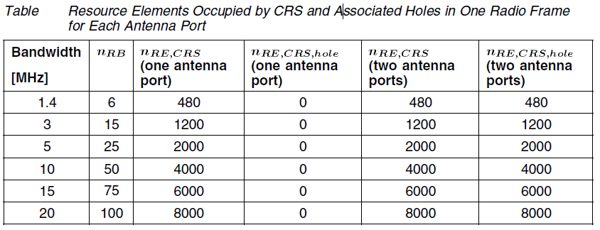
Holes are REs that must be silent because the
cell-specific reference signal is transmitted on another antenna port. With one
antenna port, the number of REs in one scheduling block occupied by the
cell-specific reference signal and holes is 8. With two antenna ports the
number is 16. The following table shows the total number of REs occupied by the
cell-specific reference signal and holes, for the bandwidths available:
LTE - Resource Structure
Time
Domain Structure
In
the time domain, the signal is structured in the following parts:
Time Domain Signal Structure
|
Structure Element
|
Description
|
|
Radio Frames
|
10 ms length
|
|
Subframes
|
1 ms length. One frame consists of 10 subframes.
|
|
Slot
|
0.5 ms length. One subframe consists of two slots.
|
|
OFDM symbol
|
Approximately 71.4 μs length. One slot consists of 7 OFDM symbols.
|
Frequency
Domain Structure
Orthogonal
Frequency-Division Multiplexing (OFDM) utilize a large number of subcarriers.
Each subcarrier is orthogonal to all other subcarriers. Subcarrier spacing is
equal to the subcarrier bandwidth, which is 15 kHz, see Figure
Resource
Element
The
smallest resource unit handled in LTE consists of the combination of:
•
The smallest time domain unit, one OFDM symbol
•
The smallest frequency domain unit, one subcarrier
This
unit is called Resource Element (RE). An RE that is not used for transmission
is referred to as a hole
Resource
Block
A
number of REs are grouped into a physical Resource Block (RB). An RB is defined
as follows:
•
In the time domain: 7 OFDM symbol times (one slot)
•
In the frequency domain: 12 consecutive subcarriers
Scheduling
Block
A
scheduling block consists of two RBs adjacent in time and with the same subcarriers.
A scheduling block is the smallest unit that can be scheduled to user
equipment.
LTE - Resource Block Flexible Bandwidth
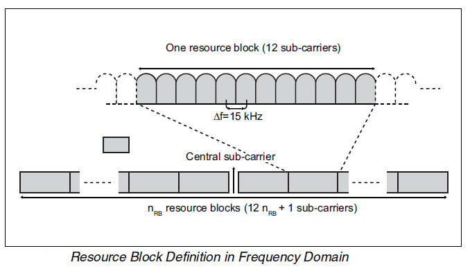
A transmitted OFDMA signal can be carried by a number of parallel
subcarriers. Each LTE subcarrier is 15 kHz. Twelve subcarriers (180 kHz) are
grouped into a resource block. The downlink has an unused central subcarrier. Depending
on the total deployed bandwidth, LTE supports a varying number of resource
blocks.
The following illustration shows resource block definition:
A
resource block is limited in both the frequency and time domains. One resource
block is 12 subcarriers during one slot (0.5 ms).
In
the downlink, the time-frequency plane of OFDMA structure is used to its full
potential. The scheduler can allocate resource blocks anywhere, even non-contiguously.
A variant of OFDMA is used in the uplink. This
variant requires the scheduled bandwidth to be contiguous, forming in effect a
single carrier. The method, called SC-FDMA, can be considered a separate
multiple access method.
A
user is scheduled every Transmission Time Interval (TTI) of 1 ms, indicating a
minimum of two consecutive resource blocks in time at every scheduling instance.
The minimum scheduling in the frequency dimension is 12 subcarriers that is the
width of one resource block in the frequency dimension. The scheduler is free
to schedule users both in the frequency and time domain. Show in Figure as
example of two users scheduled in the time and frequency domain for the
downlink and the uplink:
The
defined LTE bandwidths in 3GPP are the following:
In Table Bandwidths and Resource Blocks Specified in 3GPP
Bandwidth
|
Number of Resource Blocks nRB
|
1.4 MHz
|
6
|
3.0 MHz
|
15
|
5.0 MHz
|
25
|
10.0 MHz
|
50
|
15.0 MHz
|
75
|
20.0 MHz
|
100
|
LTE - User Equipment
Five
UE categories have been specified by 3GPP in User
Equipment (UE) radio access capabilities, 3GPP TS 36.306. Each category is specified by a number of downlink and uplink
physical layer parameter values listed in fig.
3GPP
has in User Equipment (UE) radio transmission
and reception, 3GPP TS 36.101 specified
one power class, UE power class 3, that has a maximum output power of 23 dBm.
Subscribe to:
Posts (Atom)


